VIDC Enhancer project 2012
The VIDC Enhancer project 2012 was born out of the desire to make a VIDC Enhancer board so I could end my dependence on CRT monitors and prolong the use of my Archimedes into the future by allowing them to output video signals compatible with VGA and SVGA monitors.
To that end, I could have just built a VIDC Enhancer board according to the already existing projects that are on the Internet on the late Paul Vigay's site RISCOS.org and as detailed on the Qube RISCOS servers projects page. Both of these projects are based on the work of Andreas Barth and this project is no different in that respect.
SYNC on Green
Where the project does differ is that the PCB board design also includes a simple fix for the SYNC on Green bug that is present in the A300, A400 and A400/1 series of Archimedes.
Whilst the solution to the SYNC on Green bug that I've written about works for the A400/1 series, it doesn't work for the A300 and A400 series but with a minor modification, it can be made to work and this VIDC Enhancer project has incorporated the fix into the PCB design which can be applied by the simple configuration of a pair of jumpers on the board.
With the original and modified VIDC Enhancer projects that I've referenced, along with the Aux I/O flying lead and Clock I/O, the board requires flying leads for power and optional flying leads that lead to a switch for manual override of the VIDC Enhancer software. Because my design incorporates a fix for the SYNC on Green issue, the board has access to its own 5V and GROUND lines thereby negating the requirement for the flying leads that power the circuit.
If the manual override switch is omitted from the installation and the board is configured for software control, there is only the requirement for the Aux I/O and Clock I/O flying leads to be connected simplifying the installation.
Alternate configurations
Although the board has been designed to address the SYNC on Green issue as well as providing VIDC Enhancer functionality, the A3000 does not require the SYNC on Green fix. As such, I've designed the board so that it can be configured to either be built on a riser and draw power from the motherboard directly or it can be powered by an extra set of flying leads connected to a suitable 5V and GROUND point on the motherboard.
To that end, the A3000 board can be configured identically to the original projects as referenced or built with a riser to reduce the number of connections the board requires.
If someone were to choose not to have the riser board configuration and simply cut the correct pin of the chip or motherboard trace responsible for the SYNC signal being output to the Green video signal, they could run this version of the VIDC Enhancer in exactly the same way as the original design.
I believe however that the riser board version of the design provides a neater finish and sympathetically addresses the SYNC on Green issue with no need to cut pins or trace's thereby keeping the machine in a condition where the modification could be removed and no damage would have been caused to the original circuit board. It also allows someone to retain the board in place and continue to use a 15KHz style monitor simply by altering jumpers on the motherboard and VIDC Enhancer board.
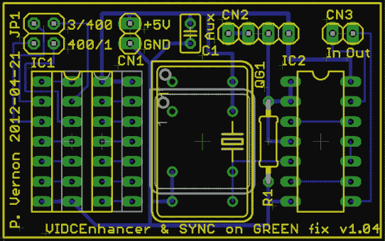
Board Layout
The board layout for the VIDCEnhancer project fits onto a PCB with dimensions of 48mm X 30mm. Depending on the configuration of the board and the target machine that the board will be fitted to, the chip fitted to IC1 will change and only where the board is built without the riser components will CN1 be fitted to allow power to be connected from an external source.
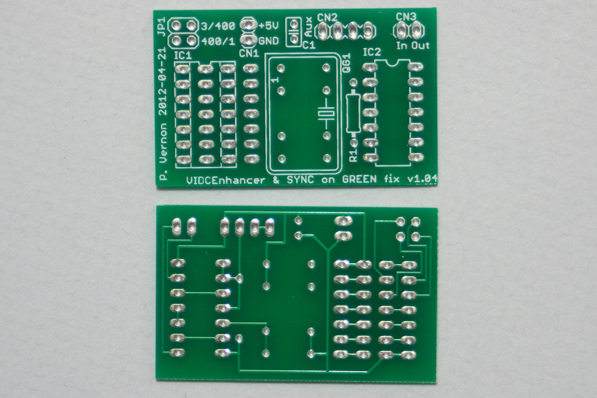
The board
The board was professionally manufactured in April/May 2012 by http://www.tecbridgecircuits.co.uk/ who took my design and prepared it for the manufacturing process at a factory in China. The boards arrived back one week ahead of schedule. I cannot say enough good things about Tecbridge and the advice and service they gave. It was simply excellent.
Installation process
There will be a small amount of solder work required to the motherboard in order to fit the VIDC Enhancer if it is supplied in the riser configuration. To clarify this, whilst the installation process for the majority of the VIDC Enhancer connections will be similar to the other VIDC Enhancer projects referenced, the addition of the riser board to address the SYNC on Green issue requires that an integrated circuit is removed from the Archimedes motherboard and replaced with a socket. The instructions for this modification for the A400/1 series can be found on the SYNC on Green page on this site. The A300 and A400 series machines use a similar fix but the IC in question on their motherboards is IC4 and the pin to cut is pin 2.
It is the intention of this project that where the board is supplied in its riser configuration, a new turned pin socket and replacement chip of the correct type will be supplied with the board so the socket can be soldered in in place of the chip on the motherboard and the VIDC Enhancer can simple be "plugged in" to the newly fitted socket and configured accordingly.
Extra solder work
The A300 and A400 series machines also require extra headers to be fitted in the position marked as PL10 on the motherboard. A set of headers will be supplied for anyone that requests the board for the A300 and A400 series Archimedes.
Switching between different Archimedes
When the board is supplied in the riser board configuration, only the chip required for the intended destination machine will be supplied in position IC1. If at some future point, the VIDC Enhancer needs to be moved to an alternate model of Archimedes, only this chip will need to be changed to match the chip being replaced on the new destination machine.
Costings and supply of board configurations
Costings have now been fully calculated and I'm able to offer the following configurations.
| Board only | £12.00 |
| Board + 36MHz Oscillator (fitted) | £16.00 |
| Kit form | £25.00 |
| Fully assembled - software control only | £27.00 |
| Fully assembled - selectable off/on/software control | £30.00 |
The Kit and Fully assembled boards contain the following components:
| Quantity | Component |
| 1 | Custom made VIDC Enhancer board |
| 1 | Custom made 36MHz Oscillator |
| 1 | 74ALS00N |
| 1 | 4-way right angle header |
| 1 | 2-way right angle header |
| 2 | Jumper shunts |
| 1 | 20K 5% 0.25W resistor |
| 1 | 100nF 50V ceramic capacitor |
| 0 or 2* | 7-way male header riser connectors |
| 1 or 2* | 2-way straight header |
| 0 or 1* | 14 way turned pin sockets |
| 0 or 1* | 74LS05N (A300/A400), SN7438N (A400/1), 74HC04N (A3000) |
| variable | All connecting cabling and connectors to suit the target machine |
| 1 | on-off-on Cherry rocker switch** |
Prices exclude the postage and packing which will be £4.95 for the mainland UK. Quantities marked with '*' are only supplied in their higher quantities for the riser board configuration. Items marked ** are not included in the software control only version.
The first run of boards is limited but I will be releasing the full design in Eagle format on this site and may produce further runs in the future depending on demand.
If anyone has any questions, please don't hesitate to contact me either through the site or via Facebook. You can also find me on the Stardot forums.
Build progress
I received the boards back from manufacture earlier than expected and I'm still awaiting the arrival of the 36MHz oscillators to complete the VIDC Enhancer part of the build. In the meantime, I built the section of the board responsible for the SYNC on Green fix to test fitting, clearance and function.
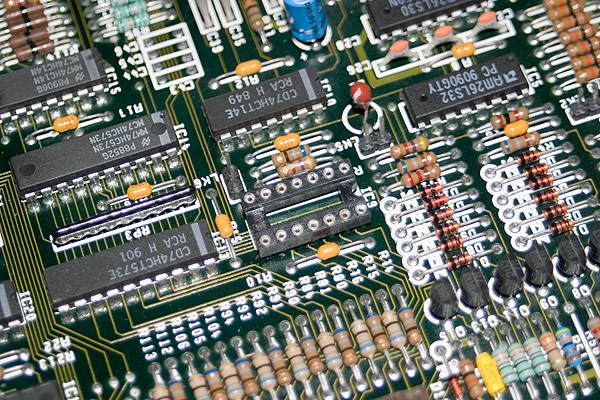
Stage 1 - Fitting a socket to the motherboard
For the A300 and A400 series, the socket must be fitted in the position of IC4 on the motherboard. The photo below shows the socket as fitted to an A410/1 in the position of IC9.
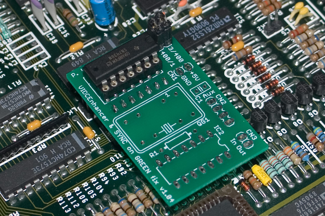
Stage 2 - Fitting the VIDC Enhancer board
The photo below shows the part made up VIDC Enhancer board fitted to the A410/1 in the IC9 socket. The chip that was in position IC9 is then transposed onto the VIDC Enhancer board. The two jumpers at the top of the photo show the SYNC on Green fix configured to output the SYNC on Green signal. For VGA monitors that do not display the Green element of the RGB output when SYNC on Green is present, either the jumper marked 3/400 should be removed for the A300 and A400 series and the jumper marked 400/1 should be removed for the A400/1 series machines.
Stage 3 - Testing the SYNC on Green fix
Stage 4 - Testing the clock signal switching
After building up the board a little further, still without the 36MHz oscillator, the switching circuitry can be tested to check that the 24MHz VIDC clock signal is switched off when the VIDC enhancer board is enabled. This requires that the board is connected to the CKSYS and CKVIDC pins on the motherboard so that the control over the 24MHz clock signal to the VIDC chip is controlled by the VIDC Enhancer.
By shorting pins 3 and 4 of CN2 (the connector to the left of the Clock I/O pins), the VIDC Enhancer board should switch the output of clock signal from the 24MHz frequency to the 36MHz frequency of the on board oscillator. Because the oscillator is not yet fitted, we simply expect that there will be a loss of video signal when the pins are shorted and that is exactly what we see.
Stage 5 - Testing the 36MHz clock
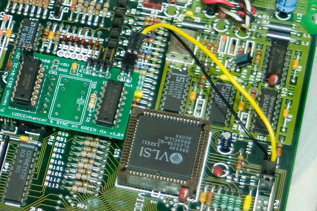
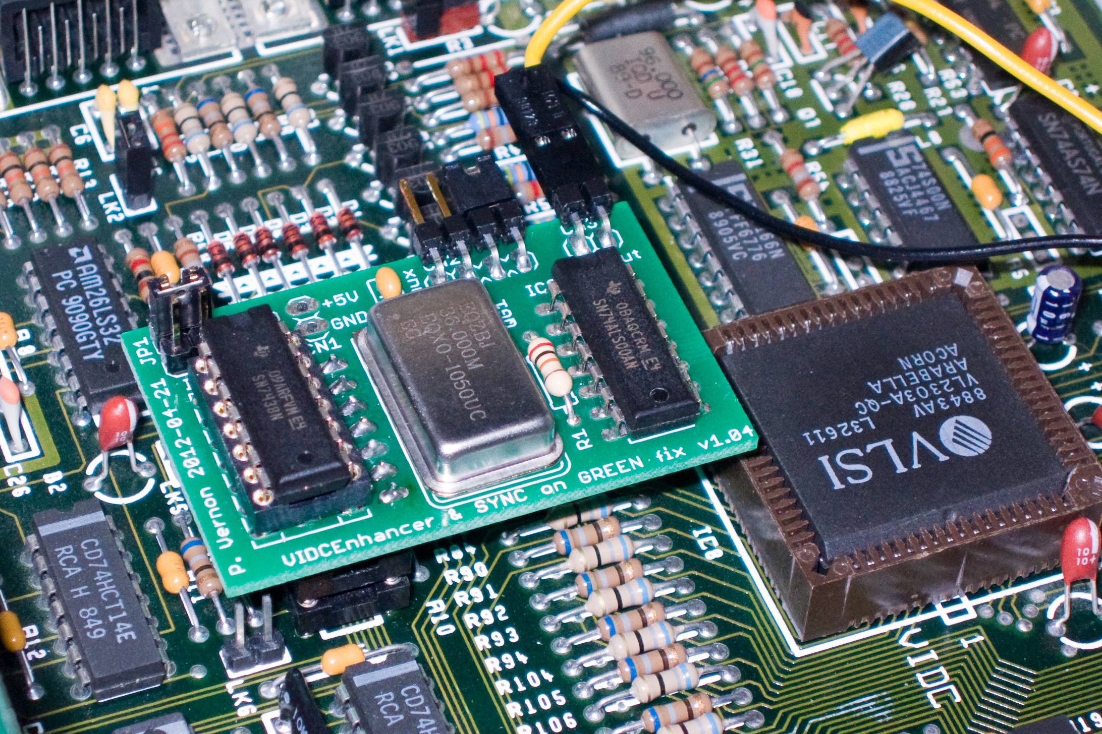
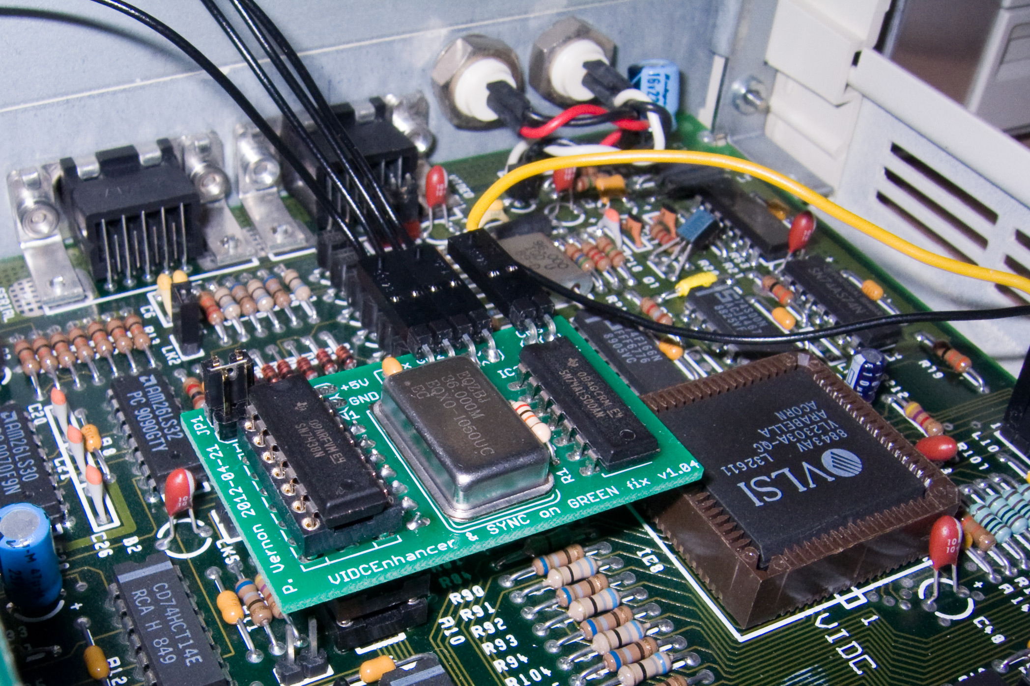
On the 7th of June, the 36MHz oscillators arrived so I've been able to fit one to the test board and complete testing of the VIDC Enhancer. The configuration in the photo below shows a simple jumper connecting pins 3 and 4 of the connector CN2 together which forces the VIDC Enhancer to output the 36MHz clock signal to the VIDC chip (Arabella) located on the right of the photo. You can click on the photo to show the high resolution version of the image.
The final stage now is to fit the Aux connector to the board so that it can be controlled by software or manually overridden using a 3-position switch.
Stage 6 - Testing the software control
The final stage of the VIDC Enhancer project is to test the software control. To do this, I used the VIDCEnhancer software written by Andreas Barth by placing the VIDCEnhancer module into the PreDesk folder of the Uniboot structure. This module is then soft-loaded and intercepts all mode changes triggering the Aux 1 pin on the Aux I/O header to go high or low. Connecting this pin to the pin marked Aux on CN2 can then enable the software to control the switching of the 24MHz and 36MHz clock signals feeding one of them to the VIDC chip as required.
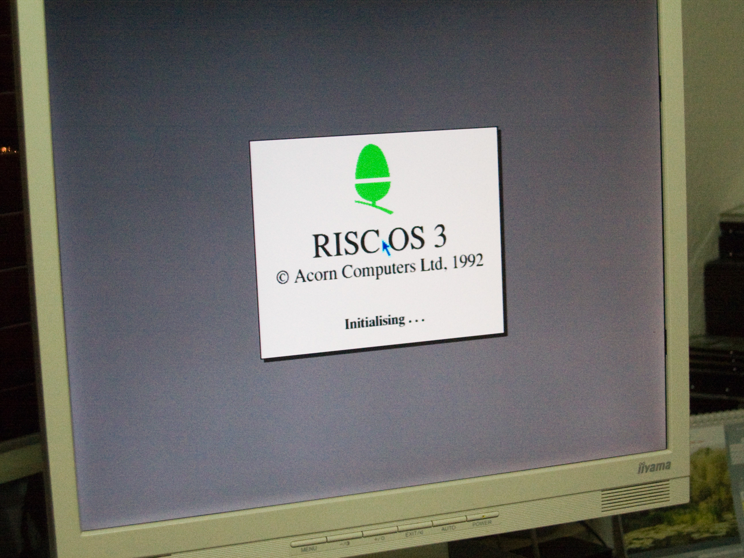
Finally, how does it look? Well, here's a shot of my IIyama E430S LCD monitor displaying the A410/1 booting into MODE 31 which has a resolution of 800x600 and a 16 colour palette.
Translate this site
VIDC Enhancer software
The Retro-kit VIDC Enhancer board is compatible with all the VIDC Enhancer software that uses the Aux1 pin of the Archimedes to control the clock selection of the board. This includes Andreas Barth's VIDC project software which this project is based on and the Atomwide and Beebug VIDC Enhancer software.
- AutoVIDC+ - updated AutoVIDC (ADF image in a SparkFS archive)
- AutoVIDC - by Andreas Barth (Original Spark archive)
- Atomwide VIDC Enhancer software (ArcFS archive)
- Beebug VIDC Enhancer software (ArcFS archive)
RISC OS MODE control software
- !Modes - Replacement MODE selector (Spark archive)
- !CustomVDU - Create custom screen modes (Spark archive)
NOTE: All these downloads are suitable for RISC OS based computers only.
VIDC Enhancer Eagle files
The VIDC Enhancer and Sync on Green board layout was created using Eagle PCB design software from Cadsoft and the project files can be downloaded below.