Adding an IDE podule to an ARM3 upgraded A3010
Whilst in a standard A3010, adding an IDE podule to it is a simple matter of plugging one into the 8-bit podule expansion sockets on the motherboard, it becomes much more difficult where the A3010 has been upgraded with an ARM3 processor on a daughter board.
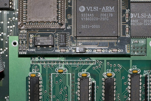
The photo below illustrates how the IDE podule overlaps the Adelaide board with its original ARM2 chip in place.
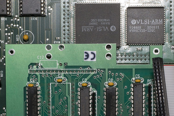
So when the ARM2 has been replaced with a socket, the ARM3 daughterboard cannot be fitted correctly and the two boards overlap to an even greater extent.
Clearly, to allow the IDE podule and the ARM3 daughterboard to fit into the A3010 at the same time and still function, some work needs to be done. Thankfully, the particular IDE podule to be fitted doesn't have much in the way of functional circuitry in the area that overlaps.
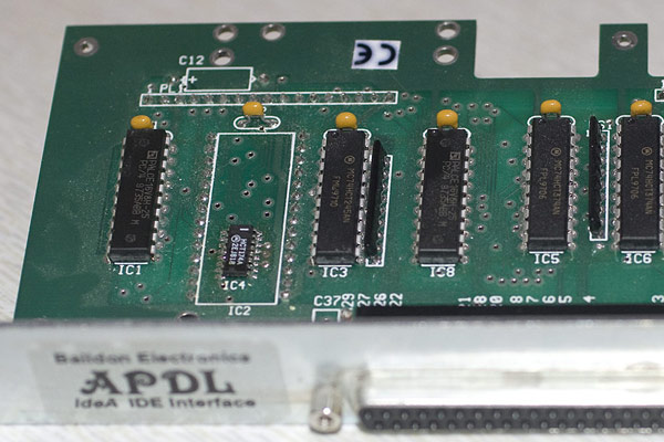
Other than the capacitor C12, there are no components in the area needing removal, however there are some PCB tracks on the underside of the board that will be cut. The modification then involves relocating the capacitor C12, cutting off the overlapping PCB and then repairing any tracks that have been cut to restore functionality to the board.
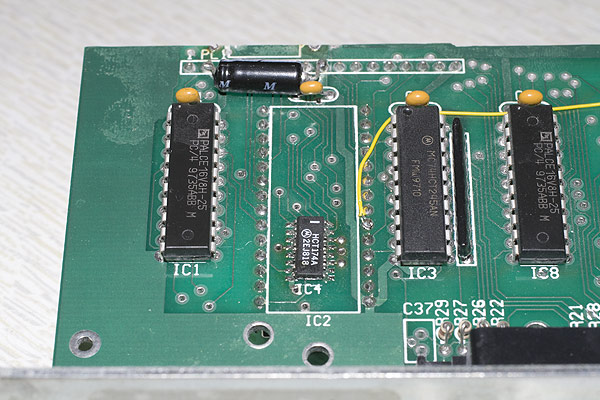
To cut the PCB, it should be firmly mounted in a vice and then a suitable cutting tool should be used. I used a Dremel with a diamond coated circular cutting blade on the slowest setting to provide a neat cut across the board. Once cut, a small file should be used to smooth off any sharp edges. The photo's below show how the IDE podule was cut down to size with the capacitor relocated onto the top of the PCB.
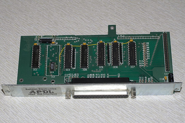
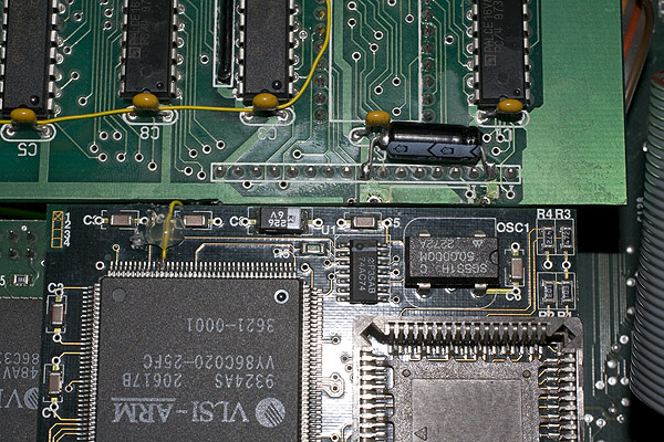
If you look closely in the photo below, the leading edge of the PCB is not straight. This is intended. The recessed part was extended to make way for the ARM3 ALE link and the extended part of the PCB carries tracks on the underside which I have attempted to retain as much as possible. In the end, only one track was cut in the process of making the board fit and the yellow Kynar wire wrap which was used to repair that track can be seen in the shot.
Finally, fitting the board shows how the recessed part allows for the ALE line to pass from the underside of the ARM3 PCB to the ARM3 chip and gives enough clearance for both items to fit.