Upgrading an Adelaide A3010 to ARM3 power
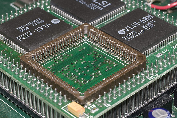
Very early examples of the A3010 shipped prior to the completion of the ARM250 chip which was the first ARM "System on a Chip" device. As such, the early examples contained a mezzanine board which carried all of the original ARM2 chipset together with the enhanced IO support that was added to Acorn's machines from the A5000 onwards. The ARM2 mezzanine board was code named "Adelaide" by Acorn and the schematic for the Adelaide board was code named "Heron".
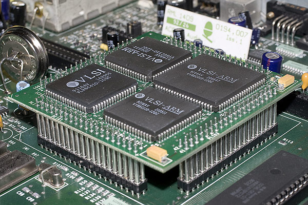
In mid-2013 Andrew McConville sent his early A3010 to me to document the mezzanine board and perform some upgrade work including changing the battery, installing an IDE podule and potentially replacing the ARM2 chip with a socket and an ARM3 daughterboard.
Whilst running Andrew's A3010, it became apparent that the MEMC chip was failing as after a period of time, the video signal started to become unstable. Using some Freeze spray on the MEMC chip restored stability to the video signal until the effects of the freeze spray wore off.
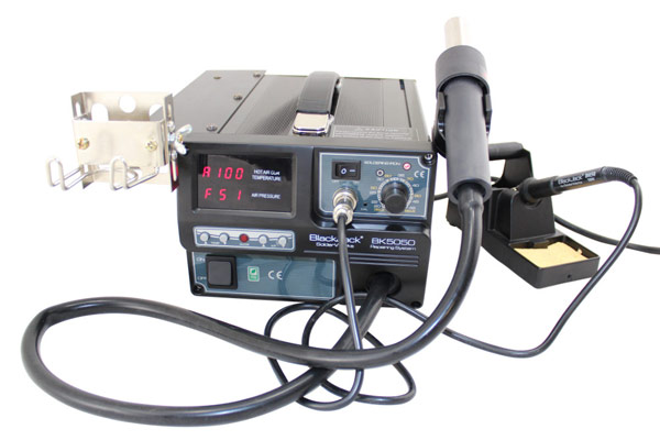
Because of the issues with the MEMC chip, we decided that whilst I was working on the Adelaide board replacing the MEMC chip, I should go ahead and remove the ARM2 CPU replacing it with a socket. To achieve this modification, a significant amount of solder work with a hot air rework station is needed because the ARM2 processor is soldered directly onto the Adelaide PCB. Do not attempt these modifications without using something similar.
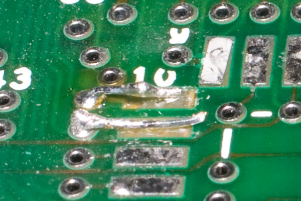
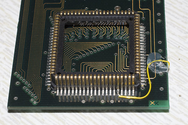
Due to the age of the Adelaide board, the work involved in removing the chips requires a gentle touch however whilst being as careful as possible, it's almost impossible to avoid PCB damage.
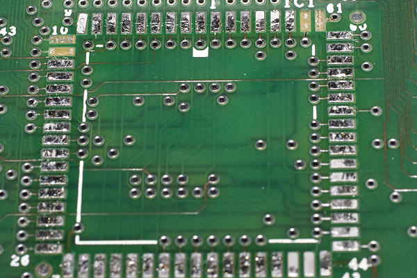
Thankfully, the repair of these pads was relatively simple due to the proximity of the PCB via's close by. Using very small pieces of wire, the pads could be replaced as shown in the photo below:
Once the pad repairs were in place, a new MEMC chip could be re-soldered to the Adelaide board.
With the MEMC chip replaced and the ARM2 chip removed, a socket needs to be fitted to the Adelaide board. Due to the space available on the Adelaide board and the locations of some of the passive components, the socket must be modified to fit on the Adelaide board. The photo below shows the width of the socket edge as standard on the left and the edge as it is needed in order to fit onto the PCB after a significant amount of work with a fine file.
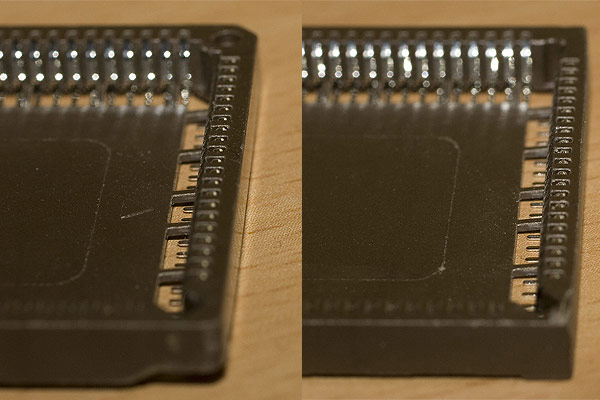
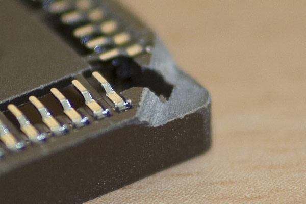
One of the corners of the socket also needs some work in order to clear one of the capacitors on the Adelaide PCB.
The socket can then be soldered into place on the Adelaide board. I did this with the hot air rework station but had to cut out the base of the socket after it had been soldered into place to access a couple of the pins which had formed a solder bridge. Great care must be taken when doing this so as not to distort the socket to ensure that connectivity to the ARM2 chip or ARM3 daughterboard isn't compromised.
About the ARM2 on the A3010
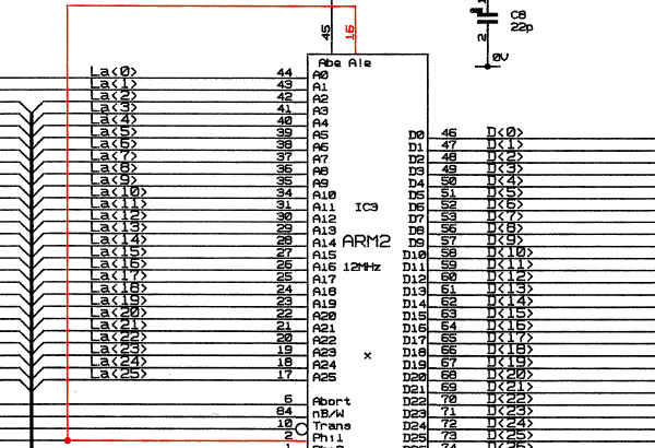
The A3010's that were fitted with an ARM2 CPU had a quirk of the hardware that required the ALE (Address Latch Enable) input to be tied to the Phase 1 clock (Phi1).
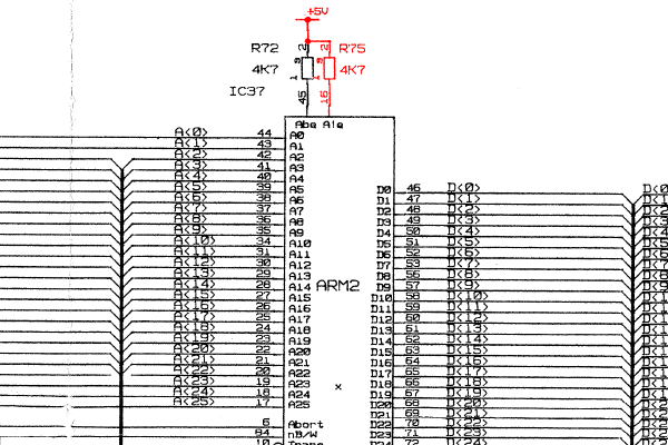
All other Archimedes including the A5000 had the ALE input on the ARM2 and ARM3 processor tied high.
About the ARM3 and 3rd party daughterboards
Because of the rarity of the Adelaide board based A3010's, there was little demand for purpose built ARM3 upgrade boards and so no-one made them specifically for the A3010. This meant that only a small number of ARM3 daughterboards were suitable for fitting to the A3010 due to space restrictions and many of those (but not necessarily all) required modifications for them to work correctly.
The ARM3 datasheet details the processor as having an internal resistor fitted which is used as a pull-up on the ALE line. As such, many ARM3 daughter boards simply left the ALE pin disconnected allowing ALE to be pulled high by the internal pull-up. This is because the ALE line on all the machines that these daughterboards were designed for simply pulled ALE high on the ARM2 processors as shown in the schematics above.
With the A3010 however, leaving the ALE pin disconnected results in a non-booting computer as it cannot access the RISC OS ROMs to boot. This means that the ARM3 daughterboard must be modified to make things work.
As all the ARM3 daughter boards were all built and sold by third parties, there are few, if any schematics for these boards available online so it's down to some manual checks with a multimeter to determine whether the ARM3 board will work or can be suitably modified. The board should first be checked to see if a modification is needed. A simple continuity test between pin 16 on the ARM2 plug and pin 29 on the ARM3 will determine if a modification is required. If there is no connection between these two points, the board will require modification.
If the ARM3 needs to be modified, it should be checked to ensure that pins 26, 29 and 30 on the ARM3 are not connected to each other. If pin 29 (ALE) is not connected to the other two pins then the ARM3 board will be suitable for modification.
I have tested the Watford ARM3, IFEL A3000 ARM3 and Simtec ARM3 daughterboards and none of them have the ALE link in place so would all require a modification.
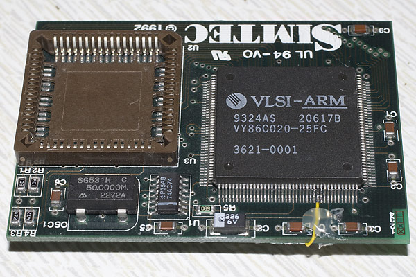
Modifying a Simtec ARM3 daughterboard
The modification to the ARM3 daughterboard is actually quite simple. Pin 16 of the ARM2 plug on the underside of the daughterboard must be directly connected to pin 29 of the ARM3 chip on the top side of the daughterboard. As you can see from the photo, this wire is quite fiddly to fit but once in place will link the ALE signal from the A3010 to the ARM3 chip allowing the ARM3 chip to correctly access the A3010's RISC OS ROM's. Also, a small amount of hot glue is used to fix the wire into place to ensure that movement will not break the delicate solder work.
The photo below shows pin 16 of the plug with some Kynar wire wrap soldered to it. A dab of glue from a hot glue gun holds the wire firmly in place.
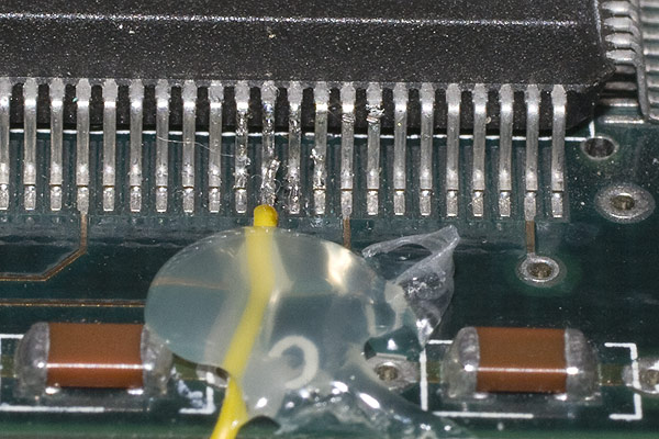
On the top side of the ARM3 daughterboard, pin 29 of the ARM3 needs the link from beneath to be made. Again, a dab of hot glue holds the wire firmly in place ensuring that the solder joints are subject to less movement.
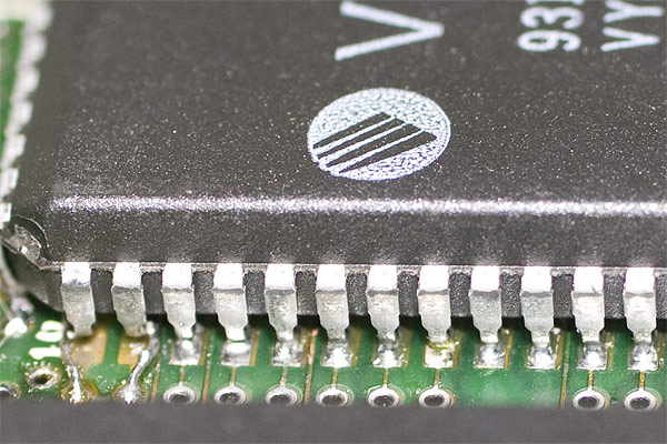
Here's a detailed shot of the solder work on pin 29 showing just how fine the pins on the ARM3 are.
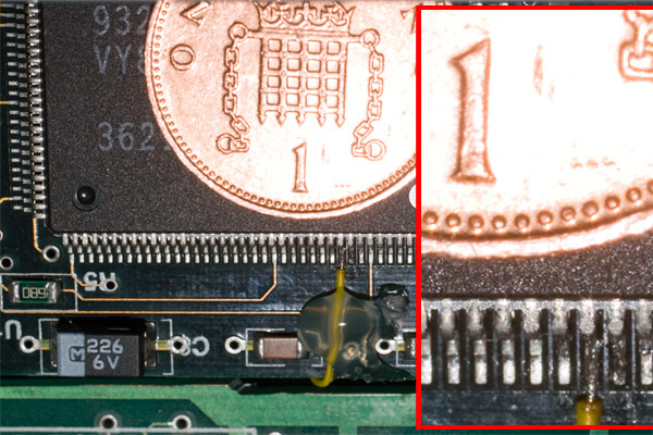
You can see in the photo below a 1 pence coin used to establish the scale of the size of the ARM3 and its leads in the photo.
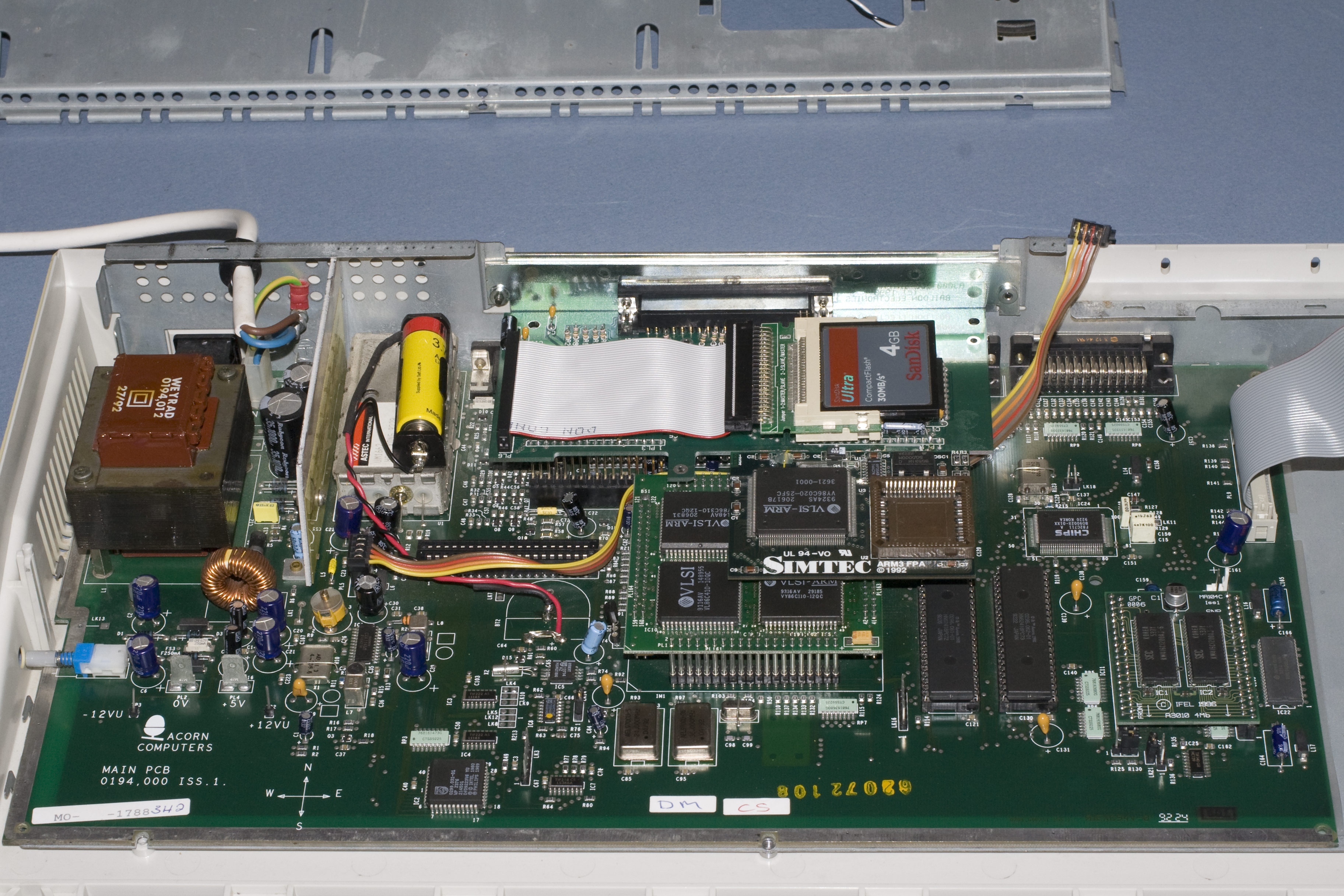
Finally you can see the ARM3 board fitted to the A3010 together with a modified APDL IDE podule to give the machine 4*512MB partitions of hard drive space.
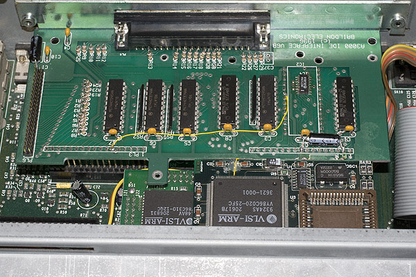
Even with the modifications to the IDE podule, the clearance between the two boards is quite small.
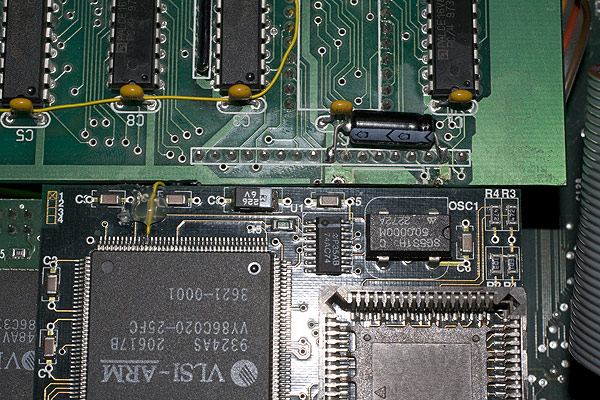
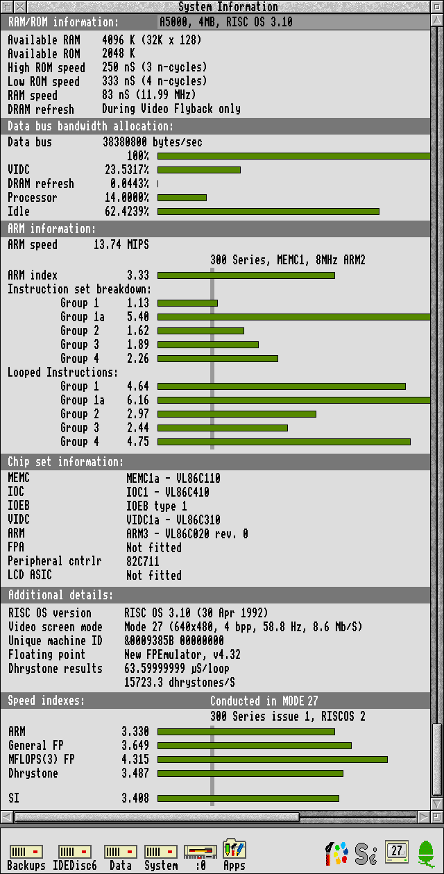
Once the modifications are complete, the A3010 will be recognised by !ArmSI as an A5000 because it has exactly the same memory bus speed of 12MHz, an ARM3 CPU fitted and finally, the later I/O controller fitted allowing for IDE (only in the A3020, A4000 and A5000) and high density floppy drive support. In essence, fitting an ARM3 upgrade to an Acorn A3010 turns it into an A5000 with a single box form factor and built in joystick support!
The ultimate retro Archimedes gaming machine!
Thanks
I'd like to thank Steve3000, Sirbod and Steve Picton for providing advice, encouragement and specialist knowledge whilst working on this A3010.
Most of all, my thanks go to Andrew McConville for allowing me to work on such a rare computer from his collection and trusting that I wouldn't destroy it completely!
Translate this site
Acorn A3010
A3010 ARM3 Performance